1.0 PURPOSE:
2.0 SCOPE:
This procedure applies for Integrity test of HEPA Filters at (Company name).
3.0 DEFINITIONS:
4.0 RESPONSIBILITY:
4.1 Engineering personnel shall responsible for Integrity test of HEPA Filters.
4.2 Engineering head shall responsible to ensure compliance.
5.0 PROCEDURE:
5.1 Frequency:
5.1.1 Integrity test of HEPA Filters should be performed after every six month or after replacement of Filter.
5.1.2 HEPA Filter replacement frequency should be whenever the filter got damaged or choked up.
5.2 Acceptance criteria:
5.3 Instrument to be used:
5.3.1 Suitable pneumatic or thermal aerosol generator to provide appropriate challenge aerosol concentration in the appropriate size range.
5.3.2 Aerosol photometer with a nominal sampling flow rate of 28.3 L/min (1 CFM) and with a sampling probe of square or rectangular configuration, whose inlet air velocity approximates the velocity of the air exiting filter.
5.4 Test aerosol type:
5.5 Test procedure:
5.5.1 Airflow velocity test should be established and qualified prior to performing this test.
5.5.2 Introduce the aerosol into the air supplied to the filter or filter under test in a manner that it will produce a uniform challenge concentration over each filter’s surface.
5.5.3 Aerosol used for the test should be poly disperse in nature and capable of dispersing smaller particles of sizes between 0.3 to 0.7µ.
5.5.4 Measure the concentration of the challenge aerosol immediately upstream of the filters under test using a photometer whose sensitivity is adjusted to a baseline of 100%.
5.5.5 Scan the entire face of filter for leaks using the probe. It should be held approximately 3 cm from the filter face during scanning using slightly overlapping strokes and also the area scan rate should not exceed 5 cm/sec (for the scanning probe size of 3cm x 3cm).
5.5.6 Scanning should be performed over the entire downstream face of the filter, the perimeter of each filter, the seal between the filter frame and the grid structure including its joints.
5.5.7 If scanning to be performed for more number of filters if up steam concentration varies significantly over the time verify the upstream aerosol concentration again and immediately scan filters for downstream concentration.
5.5.8 Record the readings displayed in the photometer if required size and location where the maximum leak is identified to be recorded in a diagram.
5.5.9 Measurements of the aerosol upstream of the filters should be repeated at reasonable time intervals between and after scanning for leaks to confirm the challenge aerosol concentration.
5.5.10 Any leakage greater than the specified limits as in 5.2.1, of the upstream challenge aerosol concentration is considered unacceptable and needs repair and resetting. Repair patches on the HEPA Filter should not exceed a maximum of 5% on the total filter and maximum width or height of any patch should not exceed 1.5 inches.
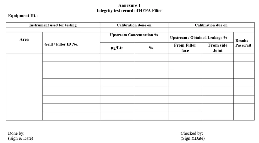
5.5.11 Note down the details and values as per the Annexure-I.
5.5.12 Note: The Concentration of the aerosol challenge upstream of the filter should be between 20 mg/m3 to 80 mg/m3.
6.0 ABBREVIATIONS:
6.1 SOP – Standard Operating Procedure.
6.2 ENG – Engineering Department.
6.3 % – Percentage.
6.4 mg/m3 – milligram per meter cube.
6.5 pg/liter – Microgram/liter.
6.6 PAO – Poly alpha olefin.
6.7 HEPA — High efficiency particular air.
7.0 REFERENCES:
Nil.
8.0 LIST OF ANNEXURES:
Annexure-I: Integrity test record of HEPA Filter.