
1.0 PURPOSE:
2.0 SCOPE:
This procedure applies for Air flow Pattern visual test at (Company name).
3.0 DEFINITIONS:
Nil.
4.0 RESPONSIBILITY:
4.1 Engineering personnel shall responsible for Air flow Pattern visual test.
4.2 QA personnel shall responsible to ensure compliance.
4.3 Engineering head shall responsible to ensure compliance.
5.0 PROCEDURE:
5.1 Frequency:
5.1.1 The test shall be carried out In-house or approved external agency initially at every 24 months.
5.2 The airflow visualization can be performed by any one of the following five methods:
5.2.1 Airflow visualization tracer threads method.
5.2.2 Airflow visualization tracer injection method.
5.2.3 Airflow visualization by image processing technique.
5.2.4 In house method (using titanium tetra chloride solution).
5.2.5 In house method (Dry Ice).
5.3 Airflow visualization by tracer threads method:
5.3.1 This test is carried by observing behavior of fiber threads such as silk threads / single nylon fibers or flags or thin film tapes and recorded by storage devices such as video camera, chemical films, disks or tapes.
5.3.2 These fiber threads or flags or film tapes are placed on the tip of support sticks or mounted on the crossing point of thin wire grids in the airflow.
5.3.3 This visually indicates airflow direction and fluctuations due to turbulence.
5.4 Airflow visualization by tracer injection method:
5.4.1 This test is carried by observing the behavior of tracer particulate matter which are illuminated by high intensity light sources and recorded by storage devices such as video camera, chemical films, disks or tapes.
5.4.2 The tracer particles are generated from material such as Deionized (DI) water, sprayed or chemically generated alcohol / glycol.
5.5 Airflow visualization by image processing technique:
5.5.1 This test is carried by processing particle image data on video frames or films, provided quantitative characteristics of airflow by way of two-dimensional air velocity vectors in the area.
5.5.2 This process requires a digital computer with suitable interfaces and the appropriate software
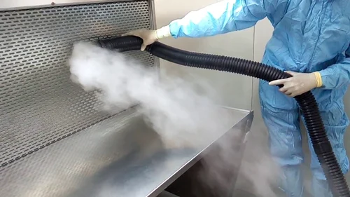
5.6 In house method (Dry Ice):
5.6.1 Ensure that the AHU’s / LAF is switched ON well before carrying the activity.
5.6.2 Place the nozzle of the dry ice generator under the supply filter.
5.6.3 Track the direction by taking a photograph or by other suitable video devices.
5.6.4 Adjust the air velocity if smoke returns upward / back flows due to turbulence and carry out the test after necessary adjustments.
5.7 Clean the area after completion of the test.
5.8 The following information and data shall be recorded in the test report:
5.8.1 Identification of apparatus operator.
5.8.2 Identification of test apparatus and their calibration status.
5.8.3 Type of tests, method of visualization and test conditions.
5.8.4 Visualization point locations.
5.8.5 Image stored on photographs or video cassettes, or raw data for each measurement (in case of the image processing technique or of the measurement of velocity distributions), if specified.
5.8.6 Occupancy state(s).
5.8.7 A plan of the exact location of all apparatus should accompany the flow visualization report.
6.0 ABBREVIATIONS:
6.1 SOP — Standard Operating Procedure.
6.2 ENG — Engineering Department.
6.3 PAO — Poly Alpha Olefin.
7.0 REFERENCES:
7.1 ISO 14644-3
7.2 Video graphic CD
8.0 LIST OF ANNEXURES:
Nil.