
1.0 PURPOSE:
2.0 SCOPE:
This procedure for temperature and RH mapping is applicable to all controlled areas (quarantine, material staging, FG stores, RM rejected rooms etc.) and Equipments (Incubator, stability chamber, Cooling cabinet etc) at (Company name).
3.0 DEFINITION:
Temperature and RH Mapping: Gathering of temperature and Relative humidity (RH) data at several points within a defined space/equipment and time.
4.0 RESPONSIBILITY:
5.0 PROCEDURE:
5.1 Temperature and RH mapping is to be carried out by using calibrated temperature sensor or data logger. RH mapping shall be considered wherever applicable.
5.2 Temperature and RH mapping of new area and equipments shall be executed through protocol and mapping shall be done for 03 consecutive days (72 hours).
5.3 Remapping of area and equipments shall be performed as per the procedure mentioned below and study shall be carried for 24 hours.
5.4 For material storage area (e.g. quarantine, material staging, RM store etc.) remapping shall be performed with 05 numbers of data logger/sensor (01 at each wall and 01 data logger/sensor shall be placed near the hot point).
5.5 For areas (other than material storage area) like compression, coating, packing, process corridor etc., remapping shall be carried with 01 number of data logger/sensor.
5.6 Procedure for assigning of remapping reference number:
5.6.1 Remapping of area & equipments shall be carried out as per periodic qualification/validation schedule for equipments/Area.
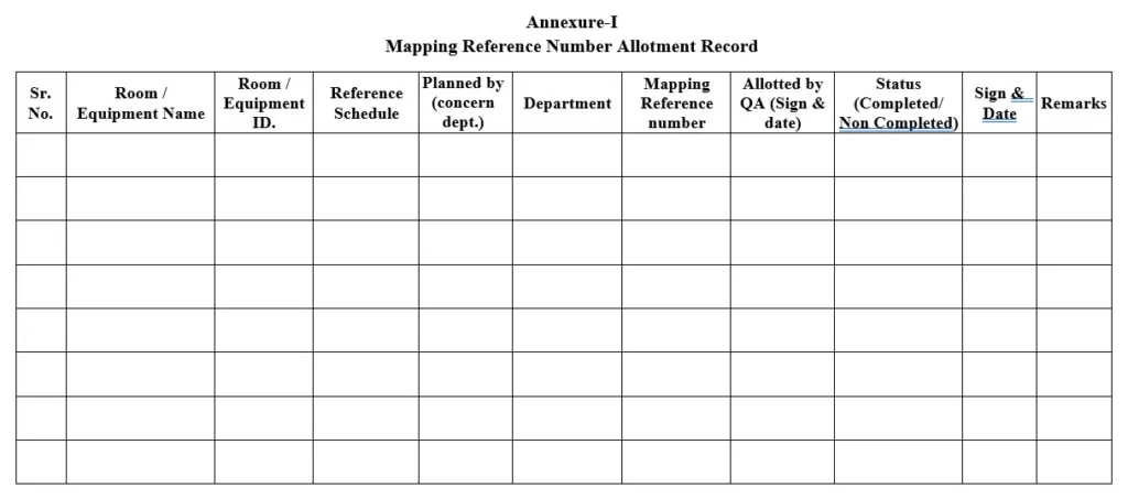
5.6.2 User department shall fill the Mapping reference number allotment record as per Annexure-I for individual equipments/area as per requalification schedule,
5.6.3 QA shall allot the Mapping reference number for individual equipments /area as mentioned below:
TRM/YY/ZZZ.
Where,
TRM – Temperature and RH mapping
YY – last two digit of the year.
ZZZ – serial number, starting with 001 and so on.
5.6.4 Remapping activities shall be carried after allotment of mapping reference number and after completion of activity, status of remapping shall be captured in Annexure-I.
5.7 Procedure for selection and placing of data logger/sensor inside the room/ equipment:
5.7.1 The mapping sensor should cover area where the temperature excursions could be more i.e. near the entrance, near the windows where direct sunlight exposes, near to walls directly exposed to the atmosphere, near to the heat generated area from lights and area near to the air conditioners and near the control and monitoring sensor.
5.7.2 Data logger/sensor should be arranged in a grid fashion along the width and length of the area so that the area is reasonably covered with data logger/sensor locations every 5-10 meters. However for area having less than 5 meters, data logger/sensor should be located at start and end of the length and width. Use additional sensors if required.
5.7.3 If the ceiling height is 3.6 meters or less, position of data logger/sensor should be directly above one another at high and low level.
5.7.4 If the ceiling height is greater than 3.6 meters, data logger should be arranged in vertical arrays at the bottom, middle and top of the space. For instance, for a storage area six meters in height, three data logger/sensor should be positioned in each grid location heights of 1.8 meters, 3.6 meters and 5.4 meters.
5.7.5 For the equipment’s ((Incubator, stability chamber, Cooling cabinet etc), spaces less than 2 m3 in volume, up to 9 (nine) sensor shall be placed and up to 15 sensors shall be placed for spaces between 2 m3 to 20 m3 in volume. Use additional sensors if required.
5.7.6 If the volume is more than 20 m3, then minimum 15 sensor shall be placed for mapping. Use additional sensors if required.
5.7.7 The equipment of capacity ≤ 500 litre, minimum two sensor shall be placed for temperature and RH (if applicable) mapping.
5.8 Temperature mapping procedure for room/Equipment:
5.8.1 Allow the room/equipment to get stabilize at the required temperature & RH (if applicable).
5.8.2 Select the required number of data logger/temperature sensor as per room area or volume.
5.8.3 Place the required number of data logger as per the procedure mentioned above (step No. 6.7).
5.8.4 Ensure the tip of the sensor shall not be touched to any surface inside the room/equipment.
5.8.5 Switch ON the data logger and kept it to record the room temperature and RH (if applicable) for minimum 24 hours at a time interval of 30 minutes.
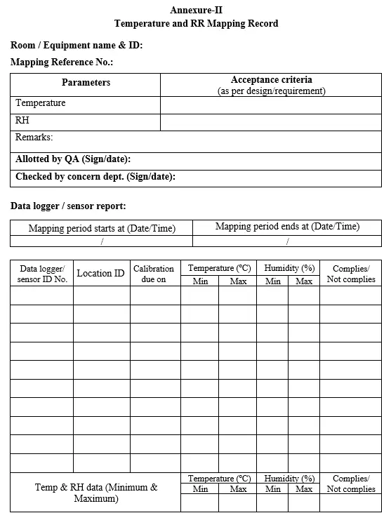
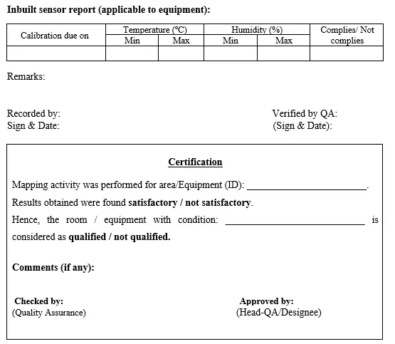
5.8.6 The temperature and RH data shall be printed. Record the data in format for Temperature and RH Mapping record as per Annexure-II.
5.8.7 Acceptance criteria for area/room:
For temperature: Results should be not more than 25 o C or within the range as
per design.
For RH: Results should be not more than 55% or within the range as per design.
5.8.8 Acceptance criteria for equipment:
5.8.8 Acceptance criteria for equipment:
For temperature: Results should be within the Set value ± 2 o C or within the range
as per design.
For RH: Results should be within the Set value ± 5% or within the range as per design.
6.0 ABBREVIATIONS:
SOP : Standard operating procedure
oC : Degree centigrade
m3 : Cubic meter
QA : Cubic meter
RH : Relative humidity
7.0 REFERENCE:
8.0 ENCLOSURES:
Annexure-I: Mapping reference number allotment record
Annexure-II: Temperature and RH Mapping record
Also read: SOP for Mock Recall
Also read: SOP for quality risk management